Open Automotive Controller

Chameleon

A 32-pin automotive controller with open hardware and firmware. Two CAN FD buses, two LIN, twelve analog inputs and six protected outputs on an Arm Cortex-M7 running TockOS, reprogrammable in the vehicle over CAN.

In development. The schematic is complete and PCB layout is under way; no prototypes have been built yet. The firmware, including the CAN bootloader, runs today on a SAM V71 development board. Electrical figures on this page come from design analysis, not measurements.
32Pin connector
2CAN FD buses
2LIN buses
12Analog inputs
6Protected outputs
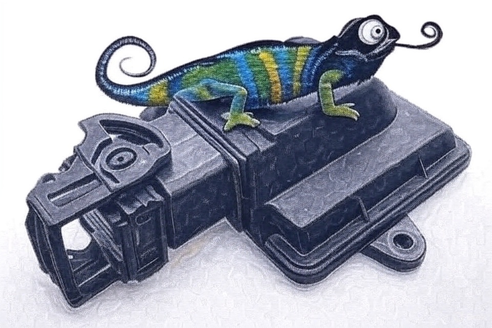
Illustration of a chameleon sitting on the Chameleon controller enclosure

Fits In Where
It Isn't Expected

Open Hardware TockOS Rust CAN FD UDS AEC-Q

Automotive controllers have always been closed: closed hardware, closed software, closed ecosystems. You buy what's available, work within what's supported, and hope the vendor's roadmap matches yours.

Chameleon is open by design. It's built from automotive-qualified parts and runs TockOS, an embedded operating system written in Rust, where each application is isolated from the others and from the kernel by the processor's memory protection.

Rust isn't common in vehicles yet. That's what the name is about: Chameleon fits into an environment where it isn't expected, and the same board can take on different jobs, such as CAN gateway, data logger or output controller, depending on the applications loaded onto it.

The housing is a standard 32-pin automotive enclosure, so there's no custom tooling. The schematic and design files will be published. Build it, modify it, learn from it.

Architecture

Chameleon block diagram CAN wake (TJA1043 INH) IGN / hold Battery In +BATT · 8 – 16 V Input Protection TVS · π filter · reverse-battery FET → protected rail to all loads 5 V Buck AP64100Q 3.3 V Buck AP64100Q Window Watchdog TPS3850-Q1 · reset + 3.3 V enable Ignition & Hold IGN (TVS protected) · MCU self-hold Sensor Supply +VEXT 5 V · ~200 mA limit · TPS7B7701 Analog Inputs ×12 IN0–5: 0–16 V · IN6–11: 0–5 V Flash Enable Forces bootloader entry TockOS Rust kernel · MPU-isolated applications Bootloader UDS over CAN FD · SHA-256 check · rollback ATSAMV71Q21B Arm Cortex-M7 · 300 MHz 2 MB flash · 384 KB SRAM ─ +5V ─ +3V3 ─ NRST · WDI ─ IGN · HOLD ─ EN · ISENSE ─ ADC ─ FLASH_EN MCAN0 ─ MCAN1 ─ UART ×2 ─ LSO[0..3] ─ HSO[0..1] ─ HSMCI ─ I²C · ADC ─ CAN0 Transceiver TJA1043 · CAN FD · bus wake · spliced, unterminated CAN1 Transceiver TJA1057 · CAN FD · split termination LIN Transceivers ×2 NCV7321 Low-Side Outputs ×4 BTF3080EJ smart low-side switches · status feedback High-Side Outputs ×2 TPS2H160A · 2 A current limit per channel · diagnostics microSD Card Logging and storage · switched 3.3 V supply EEPROM & Board Temperature M24C02 (2 Kbit) · NTC thermistor

Dashed lines are enable paths: ignition, the MCU's self-hold and CAN0 bus wake turn on the 5 V supply; the window watchdog controls the 3.3 V supply and the MCU reset. The protected battery rail feeds both converters, the sensor supply, the high-side switch and the transceivers.

32-Pin Connector · Functional Layout

A
B
C
D
E
F
G
H
1
CAN
A1 · CAN0_L
CAN
B1 · CAN0_H
CAN
C1 · CAN1_L
CAN
D1 · CAN1_H
IGN
E1 · Ignition
LIN
F1 · LIN0
LSO
G1 · LSO0
BAT
H1 · +BATT
2
SPC
A2 · CAN0_L (splice)
SPC
B2 · CAN0_H (splice)
SGND
C2 · Sensor ground
IN10
D2 · IN10 (0–5 V)
IN8
E2 · IN8 (0–5 V)
FEN
F2 · FLASH_EN (bootloader)
LSO
G2 · LSO1
HSO
H2 · HSO0
3
IN0
A3 · IN0 (0–16 V)
IN2
B3 · IN2 (0–16 V)
IN4
C3 · IN4 (0–16 V)
IN6
D3 · IN6 (0–5 V)
IN9
E3 · IN9 (0–5 V)
LIN
F3 · LIN1
LSO
G3 · LSO2
HSO
H3 · HSO1
4
IN1
A4 · IN1 (0–16 V)
IN3
B4 · IN3 (0–16 V)
IN5
C4 · IN5 (0–16 V)
IN7
D4 · IN7 (0–5 V)
5V
E4 · +VEXT sensor supply
IN11
F4 · IN11 (0–5 V)
LSO
G4 · LSO3
GND
H4 · Ground
CAN FD (faded = splice)
Analog 0–16 V
Analog 0–5 V
Sensor supply
LIN
Low-side out
High-side out
Power / ground
Ignition
Flash enable

Molex 0643340100. Columns A–F are low-current terminals, G–H high-current. Hover or tab to a pin for its signal.

Design Notes

  • Two CAN FD busesCAN0 is spliced through the connector so Chameleon can sit mid-bus without a harness change, and it can wake the board. CAN1 is a single pair with on-board split termination.
  • Inputs that suit real sensorsSix battery-range inputs (0–16 V) and six 5 V sensor inputs with clamps, plus a current-limited, switchable 5 V supply for the sensors, with its own ground return so load current doesn't shift the readings.
  • Protected outputsFour smart low-side switches and a two-channel high-side switch with a 2 A current limit per channel, each reporting faults back to the processor.
  • Built for the vehicle supply8–16 V operation, reverse-battery protection, a TVS and π filter on the input, and protection on the ignition line. Designed against ISO 16750-2, ISO 7637-2 pulses and CISPR 25 conducted emissions.
  • Low sleep currentIgnition or CAN wakes the board; asleep, the target is under 125 µA at 13.5 V (95 µA by calculation). The battery-monitor divider is switched off in sleep so it doesn't drain the battery.

Reprogram It
Where It's Installed

Chameleon runs TockOS. The kernel is written in Rust; applications can be written in Rust or C and are loaded separately from the kernel. Each one runs in its own memory region enforced by the Cortex-M7's memory protection unit, and several applications can share the CAN buses at once.

Everything can be updated from the vehicle's CAN bus with standard UDS diagnostic services, so the enclosure stays closed. Measured on the development board, CAN FD transfers write flash at about 59 KB/s.

  • UDS bootloaderISO 14229 diagnostics over ISO 15765-2 transport on CAN FD. Any standard UDS tester can drive a reflash.
  • Automatic rollbackThe kernel is checked with SHA-256 at every boot. If the check fails, the bootloader restores the previous kernel from a backup copy.
  • tockloader over CANInstall, list and remove applications over the vehicle bus with the standard Tock tooling.
  • Signed privilegesOnly an application with a valid ECDSA P-256 signature can restart the board into the bootloader.
  • Hard to brickA FLASH_EN pin on the connector forces the bootloader regardless of the installed firmware, a UART recovery path stays available, and an external window watchdog resets the processor if the firmware stops responding.

At a Glance

Microcontroller
ATSAMV71Q21BArm Cortex-M7, 300 MHz, AEC-Q100
Memory
2 MB Flash / 384 KB SRAMPlus 2 Kbit EEPROM and microSD
Operating system
TockOSRust kernel; applications in Rust or C
Networks
2 × CAN FD · 2 × LINTJA1043, TJA1057, NCV7321
Analog inputs
6 × 0–16 V · 6 × 0–5 V12-bit ADC
Outputs
4 low-side · 2 high-sideBTF3080EJ; TPS2H160A, 2 A limit per channel
Sensor supply
5 V, ~200 mACurrent-limited, switchable, with fault flag
Supply voltage
8 – 16 VISO 16750-2 code B
Operating temperature
−40 °C to +85 °CDesign target
Sleep current
< 125 µAAt 13.5 V; design target, 95 µA calculated
Wake sources
Ignition · CAN
Programming
UDS over CAN FDPlus UART recovery and SWD
Connector
32-pin Molex CMC0643340100
Enclosure
Standard automotive housingOff-the-shelf; no custom tooling
Licenses
CERN-OHL-P v2Software: Apache 2.0 / MIT

Open Hardware.
Open Source.

The schematics and design files will be published. Build it, fork it, improve it.

Follow Development on X